Table of Contents
In the Watkins area of Denver, maintaining a reliable electrical grounding system is vital for homeowner safety. Grounding provides a safe path for fault currents and lightning strikes, preventing shocks and fires. After any repair to your grounding system, verifying that it meets the 25-ohm rule becomes a critical step. This standard, outlined in the National Electrical Code (NEC) section 250.56, requires supplemental grounding electrodes to have a resistance to ground not exceeding 25 ohms. Homeowners who understand the verification process can ensure their systems comply with local codes enforced by authorities like Denver’s electrical inspectors. This article outlines the methods, tools, and best practices for Watkins residents to check their repaired grounding systems effectively.
Understanding the 25 Ohm Rule
The 25-ohm rule specifically applies to supplemental grounding electrodes, such as ground rods or plates, installed in addition to the primary grounding electrode system. According to NEC guidelines, if a single ground rod does not achieve 25 ohms or less, a second rod must be added at least 6 feet away. Verification confirms that the overall system resistance falls within this limit, ensuring optimal performance during fault conditions. In Colorado’s variable soil conditions—ranging from dry, rocky terrain in Watkins to more conductive urban soils—resistance can fluctuate, making post-repair testing essential. Transitioning from theory to practice, homeowners must employ precise measurement techniques to assess compliance accurately.
Why Verify After Repairs
Repairs to grounding systems, such as replacing corroded rods or improving connections, can alter resistance levels due to soil disturbance, new materials, or environmental factors. Without verification, a seemingly fixed system might still pose risks, potentially leading to failed inspections or safety hazards. For Watkins homeowners, local building codes align with NEC standards, and non-compliance could result in costly rework. Regular verification also extends system longevity by identifying issues early. As we move forward, the focus shifts to the necessary equipment for accurate testing.
Essential Tools for Ground Resistance Testing
To measure ground resistance reliably, specific tools are required. These instruments ensure readings align with industry standards like IEEE 81. A clamp-on ground tester offers simplicity for preliminary checks, while the three-point fall-of-potential method provides the most precise results. The following table summarizes key tools and their purposes:
| Tool | Purpose | Typical Features |
|---|---|---|
| Fall-of-Potential Tester | Primary method for accurate resistance measurement | Three terminals (E, P, C); measures down to 0.01 ohms |
| Clamp-On Ground Tester | Non-invasive testing on existing systems | Clamp around conductor; auto-ranging up to 1500 ohms |
| Auxiliary Ground Rods | Reference electrodes for fall-of-potential | 10-foot rods; copper-clad steel |
| Multimeter | Basic continuity checks | Ohmmeter function; voltage detection |
These tools are available at electrical supply stores or online, with rental options for occasional use. Proper calibration is crucial, as outdated equipment can yield inaccurate results. With tools in hand, homeowners can proceed to the verification steps, ensuring measurements reflect true system performance.
Step by Step Verification Process
Verifying ground resistance involves systematic procedures to minimize errors. The fall-of-potential method is recommended for repaired systems due to its accuracy. Here is a numbered guide to conducting the test safely:
- Turn off all power to the electrical system at the main breaker to avoid interference.
- Locate the grounding electrode conductor at the service panel or meter base.
- Disconnect the electrode conductor from the ground rod or bus for isolated testing.
- Drive two auxiliary rods: current probe (C) 50-100 feet from the ground under test (E), potential probe (P) midway between E and C.
- Connect the tester: E to ground electrode, P to potential probe, C to current probe.
- Power on the tester and record resistance at various P positions to plot the curve; flat portion indicates true resistance.
- Reconnect the system and compare reading to 25 ohms; if higher, consult further actions.
This process typically takes 1-2 hours, depending on site conditions. For clamp-on testing, simply encircle the grounding conductor and activate—no disconnection needed, though it’s less precise in multi-grounded systems. Always document readings with photos and timestamps for records.
Safety Precautions During Testing
Electrical testing carries inherent risks, especially in residential settings with live utilities nearby. Wear insulated gloves, safety glasses, and non-conductive footwear rated for electrical work. Avoid testing during rain or thunderstorms common in Watkins’ climate. Check for underground utilities via Colorado 811 before driving probes. If underground hazards are suspected, postpone until cleared. These measures protect against shocks or strikes. Building on safety, understanding common pitfalls helps refine the process further.
Common Mistakes and How to Avoid Them
Many homeowners encounter issues like poor probe spacing, leading to erroneous high readings, or soil drying between tests, inflating resistance. Ignoring multiple measurements or failing to account for seasonal moisture variations in Denver’s semi-arid environment can mislead. Over-tightening connections may damage conductors. To counteract, follow manufacturer instructions meticulously and retest under similar conditions. If results exceed 25 ohms persistently, factors like high soil resistivity might require chemical treatments or additional electrodes. Transitioning to professional involvement ensures resolution without guesswork.
Professional Assistance for Complex Cases
While DIY verification suits straightforward repairs, complex systems—such as those with Ufer grounds or multiple rods—demand expertise. Licensed electricians use advanced equipment like data loggers for comprehensive reports. In Watkins, local professionals familiar with Denver permitting processes can perform tests compliant with Authority Having Jurisdiction (AHJ) requirements. They provide stamped documentation for inspections. Homeowners benefit from this when initial tests fail or for annual maintenance, bridging the gap to full compliance seamlessly.
In summary, Watkins homeowners can confidently verify their repaired grounding systems against the 25-ohm rule using structured methods and proper tools. By prioritizing safety, accuracy, and documentation, you safeguard your home effectively. Regular checks align with best practices, reducing long-term risks in Colorado’s unique environment.
Frequently Asked Questions
What if my ground resistance measures over 25 ohms? Install an additional ground rod at least 6 feet away and retest. Persistent high readings may indicate soil issues requiring professional evaluation.
Can I test with a standard multimeter? A multimeter checks continuity but not true ground resistance to earth. Use dedicated ground testers for compliance.
How often should I verify after repairs? Immediately post-repair, then annually or after major weather events affecting soil.
Does the 25-ohm rule apply to all grounding electrodes? No, primarily supplemental rods; primary electrodes like water pipes have different criteria.
Is clamp-on testing sufficient for NEC compliance? It’s useful for screening but fall-of-potential is preferred for official verification.
What role does soil type play in Watkins? Rocky, low-moisture soils here often yield higher resistance, necessitating deeper rods or enhancements.
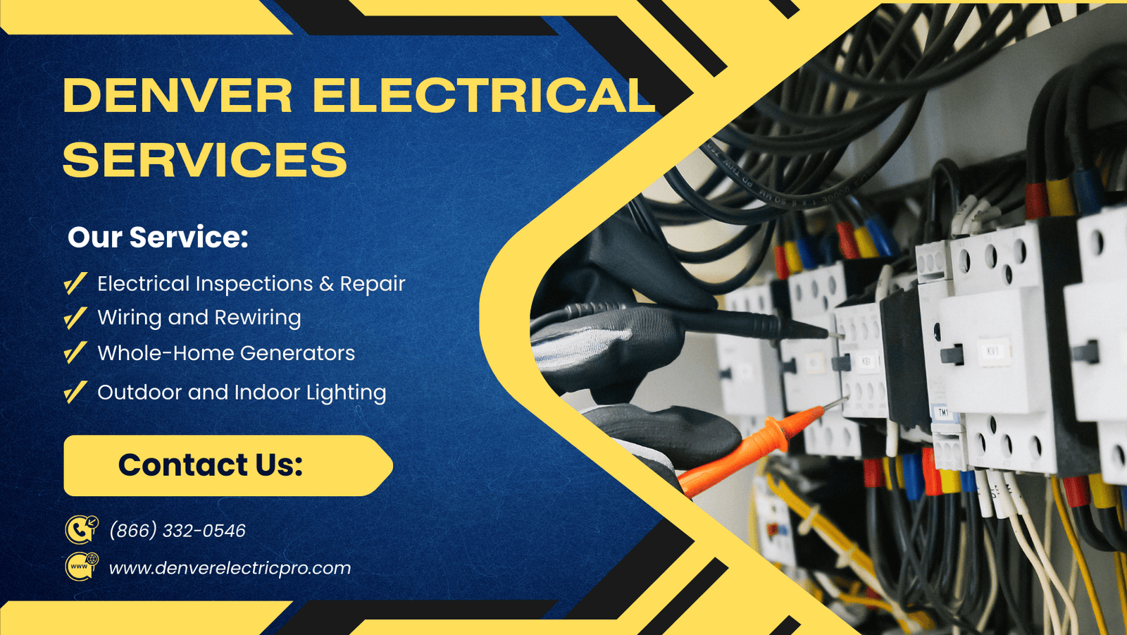
Get Your Electrical Issues Fixed Today
Are electrical issues affecting your home’s safety or increasing your energy bills? Our professional electrical services help restore reliability while improving efficiency to reduce unnecessary power usage.
Problems such as outdated wiring, faulty outlets, or overloaded circuits can quietly waste electricity and drive up monthly costs. Timely electrical repairs and upgrades can help lower your power bills and prevent more expensive issues later.
Ready to improve safety and energy efficiency? Call (866) 332-0546 now for expert electrical assistance. Please have your ZIP code ready so we can quickly connect you with licensed electricians in your area.